

DESIGN CONCEPT
The Claw-Wheel robot is a "transformable" wheel-legged hybrid robot. The folding mechanism on the center axis could be driven to transform between "Claw" and "Wheel" modes. During transformation from the "Claw" mode, the robot folds about the waist axis by two driving motors, and reconfigure the phase angles of complementary wheels to be perpendicular with each other, to form the “Wheel” mode. The process can be reversed vise versa.
CLAW MODE

The “Claw” mode is designed to maneuver across arbitrary rugged terrain, or surmount structured obstacles.
Robot under “Claw” mode has its front and rear bodies expanded and all claws’ phase angles in synchronous configuration, and climbs over obstacle surfaces with its claws.
WHEEL MODE

Under the “Wheel” mode, the robot has its front and rear bodies folded.
With support of a pair of attached, passive caster wheels, the robot acts like a general wheeled robot and is able to move rapidly across flat, smooth terrain.
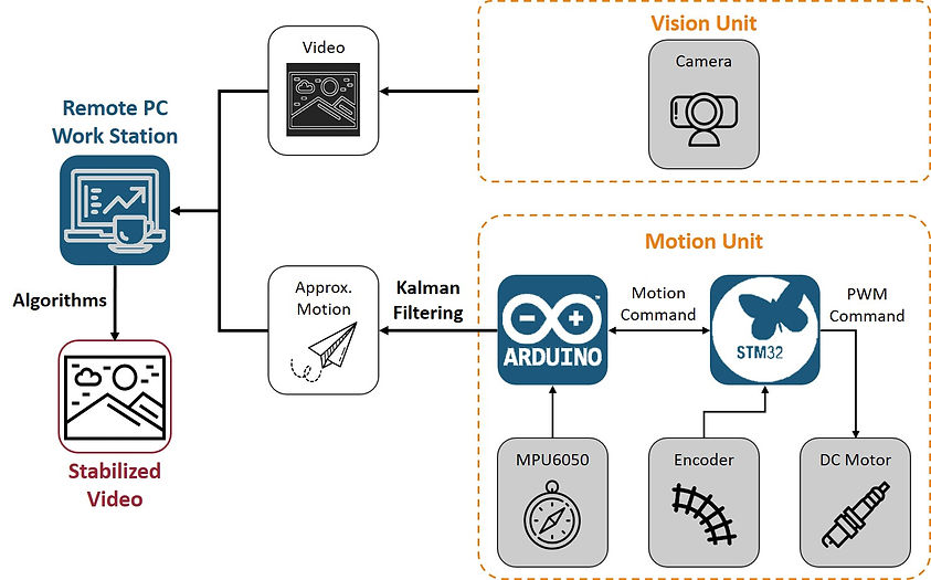
SYSTEM ARCHITECTURE
System architecture consists of a remote work station (on a computer) and an on-board system.
The vision unit is an on-board camera which captures real-time video stream from robot perception.
The motion unit combines both mobility and robot pose information retrieval. Robot motion is approximated taking advantage of on-board sensors, the MPU6050 and wheel encoders.
MECHATRONICS SYSTEM DEVELOPMENT
MOTION UNIT AND ROBOT POSE
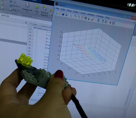
MPU6050: The IMU is rigidly attached to the camera. Given 3-axis acceleration and 3-axis angular velocity, provided by accelerator and gyroscope respectively, we use the Kalman filtering framework to obtain accurate camera orientations, roll and pitch, in real-time.
An example code is provided in following button link.
Wheel encoders: provides information of individual wheel and waist phase angles. Robot motion is approximated based on geometric configurations of the robot.
Implementation details is described in following paragraph.
MOTOR CONTROLLER MODULES
Arduino: core controller of the on-board system. Arduino receives readings from individual motor modules and MPU6050, to convert values and approximate robot motion.
Arduino also communicates with the remote work station, and sends motion commands to motor modules based on PID feedback control.
STM32: controllers of individual motor modules are selected based on feasible GPIO speed for reading a high resolution encoder (~120k pulses per revolution).
Modules count encoder pulses and send counting results to Arduino. On the other hand they also drive motors based on commands (computed PWM values) from Arduino.
Communication protocol between Arduino (master) and STM32s (slave) is I2C. Implementation code is provided in following button link.

REAL-TIME VIDEO STABILIZATION
ORIGINAL VIDEO
STABILIZED VIDEO
VIDEO STABILIZATION FRAMEWORK
Unstability in real-time video streams can be regarded as distortion, which is a result of rapid, continuous perspective variations occurred when robot is travelling across rugged terrains.
Therefore proposed 2-phase video stabilization framework is based on "reversing" such process.
In the first phase, robot motion is approximated and compensated based on on-board sensors, robot geometric configurations and signal processing techniques. In the second phase, computer vision algorithms are applied to enhance stability of processed video.

PHASE 1: COMPENSATE ROBOT MOTION

Based on robot motion estimation in previous step, we then compensate video image perspectives using perspective warping techniques.
A "warping target" is set for roll and pitch orientations. For example, in cases which we want to preserve the inherent slope of investigated environment, target of the pitch angle is set to be the smoothed value of slope angle. On the other hand, in most cases we wish to get rid of roll variations, therefore roll targets are set to zero, as demonstrated in the image.
PHASE 2: COMPUTER VISION-BASED PROCESSING

We subsequently apply feature tracking-based techniques to warped image. First, the frame image undergoes several preprocessing steps such as grayscale binary modification (to reduce graphical noise).
Then, features in current frame are extracted. The purpose is to estimate remaining frame motion, by estimating
displacements between identical feature pairs in both frames. The RANSAC algorithm is applied to rule out incorrect pair matches and regress to a more accurate frame motion.
Finally, a "cropping window" is applied in the frame and moved along previously obtained frame motion, so that inside the cropping window, features and content are maintained in same positions throughout the video sequence. The cropping window turns out serving as the output video which is guaranteed to be more stable.